|
SWMM
5.2.0
Documentation
|
|
SWMM
5.2.0
Documentation
|
SWMM 5 now has the capability to compute the amount of surface runoff flow captured by street inlet structures and sent into a below ground drainage system using the FHWA HEC-22 methodology (see Figure 1).

Figure 1. Conceptual diagram of a dual drainage system with street inlets
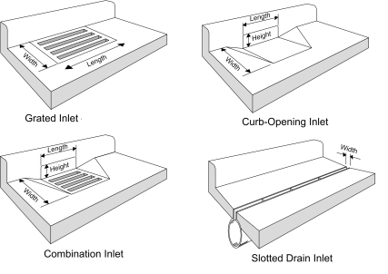
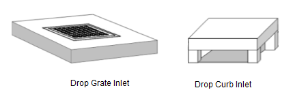
Figure 2 shows the most common types of storm drain inlets used to collect street runoff. While SWMM has some capability to model the capture efficiency of these inlets using its regulator links (orifices, weirs, and outlets), their use for this purpose is not straightforward. Many drainage engineers (and some regulatory agencies) would prefer to use the standard methodology described in the U.S. Federal Highway Administration�s Urban Drainage Design Manual (HEC-22).
 Figure 2a. Types of Curb & Gutter street inlets
  Figure 2b. Types of channel Drop inlets
To implement this feature three new sections have been added to the standard SWMM 5 input file:
[STREETS] - describes a collection of special street cross-section geometries that can be applied to a project's street conduits[INLETS] - defines a set of inlet structures that can be deployed within a project[INLET_USAGE] - specifies which conduits contain an inlet structure and the sewer node to which its captured flow is sent.The format of each section is described in detail below. In addition, a new Street Flow table has been added to SWMM's Status Report that provides the following summary information for each street conduit and inlet after a run has been made:
Some notable features of how the HEC-22 inlet analysis has been implemented within SWMM are:
Section: [STREETS]
Purpose: provides the dimensions of street cross sections used within a project.
Format:
where
| Parameter | Description |
|---|---|
Name | ID name assigned to street cross section |
Tcrown | distance from curb to street crown (ft or m) |
Hcurb | curb height (ft or m) |
Sx | street cross slope (%) |
n | Manning's n of street surface |
a | gutter depression height (in or mm) |
W | gutter width (ft or m) |
Sides | 1 for single sided street or 2 for two-sided street |
Tback | street backing width (ft or m) |
Sback | street backing slope (%) |
nBack | street backing Manning's n |

Remarks:
a = 0) then the gutter width entry is ignored.[XSECTIONS] section that includes the conduit's ID name, the keyword STREET, and the ID name of the street cross section to be used.Section: [INLETS]
Purpose: defines inlet structure designs that can be used within a project.
Formats:
where
| Parameter | Description |
|---|---|
Name | ID name assigned to an inlet structure |
Length | length of the inlet parallel to the street curb (ft or m) |
Width | width of a GRATE or SLOTTED inlet (ft or m) |
Height | height of a CURB opening inlet (ft or m) |
Type | type of GRATE used (see below) |
Aopen | fraction of a GENERIC grate's area that is open |
Vsplash | splash over velocity for a GENERIC grate (ft/s or m/s) |
Throat | the throat angle of a CURB opening inlet (HORIZONTAL,INCLINED or VERTICAL) |
GradeCurve | name of a Diversion-type curve (captured flow v. approach flow) for a CUSTOM inlet operating on-grade |
SagCurve | name of a Rating-type curve (captured flow v. water depth) for a CUSTOM inlet operating on-sag |
Remarks:
| Grate Type | Description |
|---|---|
P_BAR-50 | Parallel bar grate with bar spacing 1-7/8-in on center |
P_BAR-50x100 | Parallel bar grate with bar spacing 1-7/8-in on center and 3/8-in diameter lateral rods spaced at 4-in on center |
P_BAR-30 | Parallel bar grate with 1-1/8-in on center bar spacing |
CURVED_VANE | Curved vane grate with 3-1/4-in longitudinal bar and 4-1/4-in transverse bar spacing on center |
TILT_BAR-45 | 45 degree tilt bar grate with 2-1/4-in longitudinal bar and 4-in transverse bar spacing on center |
TILT_BAR-30 | 30 degree tilt bar grate with 3-1/4-in and 4-in on center longitudinal and lateral bar spacing respectively |
RETICULINE | "Honeycomb" pattern of lateral bars and longitudinal bearing bars |
GENERIC | A generic grate whose Aopen and Vsplash values are provided by the user. |
GENERIC type grate requires that Aopen and Vsplash values be provided. The other standard grate types have predetermined values of these parameters. (Splash over velocity is the minimum velocity that will cause some water to shoot over the inlet thus reducing its capture efficiency).Examples:
Section: [INLET_USAGE]
Purpose: Assigns inlet structures to specific street conduits.
Format:
where
| Parameter | Description |
|---|---|
Link | name of street conduit containing the inlet |
Inlet | name of inlet structure to place in street |
Node | name of sewer node receiving flow intercepted by inlet |
Number | number of inlets placed on each side of street |
Clogged | degree to which inlet capacity is reduced due to clogging (%) |
Qmax | maximum flow that inlet can intercept (flow units) |
aLocal | height of local gutter depression (in or mm) |
wLocal | width of local gutter depression (ft or m) |
Placement | AUTOMATIC, ON_GRADE, or ON_SAG |
Remarks:
Qmax value of 0 indicates that the inlet has no flow restriction.AUTOMATIC, meaning that the program uses the street network topography to determine whether an inlet operates on-grade or on-sag.Two new functional types of surface area v. depth curves have been added to represent the following shaped storage units:
 with surface area equation:
  with surface area equation:
 STORAGE section of the input file used to select these alternatives is: | Parameter | Description |
|---|---|
node | name of a storage node |
elev | elevation of the node's invert |
maxDepth | maximum height of stored water in the unit |
initDepth | initial height of stored water in the unit |
L | length of the longer side of the base of the unit |
W | length of the shorter side of the base of the unit |
Z | side slope of the unit (run/rise) |
fEvap | fraction of potential evaporation realized |
infil | optional set of infiltration parameters |
A new Type5 pump curve has been introduced to represent a variable speed pump. The curve itself specifies how the pump head decreases with increasing flow (same as a Type3 pump) at some nominal speed which represents a setting of 1.0. At any other speed setting S (as adjusted by control rules) a point with head H and flow Q on the curve becomes H*S^2 and Q*S, respectively on a speed-adjusted curve. \  \ To define a Type5 pump curve add the following line to the
 [CURVES] section of the input file
followed by lines containing name flow head values for specific points on the nominal curve.
\ Additional Condition Clause Attributes
The following additional attributes have been added to those that can appear in the condition clause of a control rule:
| Object | Attribute | Description |
|---|---|---|
| Rain Gage | INTENSITY | rainfall intensity at the current time period |
| Rain Gage | n-HR_DEPTH | rainfall depth over the past n (1 to 24) hours |
| Node | MAXDEPTH | node's rim or ground elevation minus its invert elevation |
| Node | INFLOW | node's current lateral (external) inflow |
| Conduit | FULLFLOW | Manning flow rate when conduit is full |
| Conduit | FULLDEPTH | flow depth when conduit is full |
| Conduit | LENGTH | conduit length |
| Conduit | SLOPE | conduit slope |
| Conduit | VELOCITY | flow velocity |
Named Variables
Named variables are aliases used to represent the triplet of <object type | object name | object attribute> (or a doublet for Simulation times) that appear in the condition clauses of control rules. They allow condition clauses to be written as:
where variable is defined on a separate line before its first use in a rule using the format:
Here is an example of using this feature:
Aside from saving some typing, named variables are required when using arithmetic expressions in rule condition clauses as described next. \ Arithmetic Expressions
In addition to a simple condition placed on a single variable, a control condition clause can now also contain an arithmetic expression formed from several variables whose value is compared against. Thus the format of a condition clause has been extended as follows:
where expression is defined on a separate line before its first use in a rule using the format:
The function f(...) can be any well-formed mathematical expression containing one or more named variables and any of the same math operators and functions that can be used in a groundwater flow equation or a pollutant treatment function. Here is an example of using this feature: