This chapter introduces the concept of Project Scenarios and
describes how EPANET can import and export these and other data, such
as the network map and the entire project database.
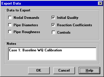
A Project Scenario consists of a subset of the data that
characterizes the current conditions under which a pipe network is
being analyzed. A scenario can consist of one or more of the
following data categories:
Demands (baseline demand plus time patterns for all categories) at
all nodes
Initial water quality at all nodes
Diameters for all pipes
Roughness coefficients for all pipes
Reaction coefficients (bulk and wall) for all pipes
Simple and rule-based controls
EPANET can compile a scenario based on some or all of the data
categories listed above, save the scenario to file, and read the
scenario back in at a later time.
Scenarios can provide more efficient and systematic analysis of
design and operating alternatives. They can be used to examine the
impacts of different loading conditions, search for optimal parameter
estimates, and evaluate changes in operating policies. The scenario
files are saved as ASCII text and can be created or modified outside
of EPANET using a text editor or spreadsheet program.
Select File >> Import >> Scenario from the main menu.
Use the Open File dialog box that appears to select a scenario file
to import. The dialog’s Contents panel will display the first several
lines of files as they are selected, to help locate the desired file.
Click the OK button to accept your selection.
The data contained in the scenario file will replace any existing of
the same kind in the current project.
EPANET has the ability to import a geometric description of a pipe
network in a simple text format. This description simply contains the
ID labels and map coordinates of the nodes and the ID labels and end
nodes of the links. This simplifies the process of using other
programs, such as CAD and GIS packages, to digitize network geometric
data and then transfer these data to EPANET.
The format of a partial network text file looks as follows, where the
text between brackets (< >) describes what type of information
appears in that line of the file:
Note that only junctions and pipes are represented. Other network
elements, such as reservoirs and pumps, can either be imported as
junctions or pipes and converted later on or simply be added in later
on. The user is responsible for transferring any data generated from
a CAD or GIS package into a text file with the format shown above.
In addition to this partial representation, a complete specification
of the network can be placed in a file using the format described in
Appendix Command Line EPANET. This is the same format EPANET uses when a project is
exported to a text file (see Section 11.7 below). In this case the
file would also contain information on node and link properties, such
as elevations, demands, diameters, roughness, etc.
The current view of the network map can be saved to file using either
Autodesk’s DXF (Drawing Exchange Format) format, the Windows enhanced
metafile (EMF) format, or EPANET’s own ASCII text (map) format. The
DXF format is readable by many Computer Aided Design (CAD) programs.
Metafiles can be inserted into word processing documents and loaded into drawing programs for re-scaling
and editing. Both formats are vector-based and will not loose
resolution when they are displayed at different scales.
To export the network map at full extent to a DXF, metafile, or text
file:
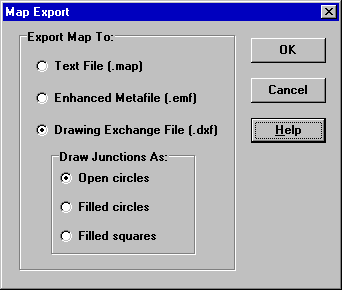
Select File >> Export >> Map from the main menu.
In the Map Export dialog form that appears (see Fig. 11.2) select
the format that you want the map saved in.
If you select DXF format, you have a choice of how junctions will be
represented in the DXF file. They can be drawn as open circles, as
filled circles, or as filled squares. Not all DXF readers can
recognize the commands used in the DXF file to draw a filled circle.
After choosing a format, click OK and enter a name for the file in
the Save As dialog form that appears.
Select File >> Export >> Network from the main menu.
In the Save dialog form that appears enter a name for the file to
save to (the default extension is .INP).
Click OK to complete the export.
The resulting file will be written in ASCII text format, with the
various data categories and property labels clearly identified. It
can be read back into EPANET
for analysis at another time by using either the File >> Open or
File >> Import >> Network commands. Complete network descriptions
using this input format can also be created outside of EPANET using
any text editor or spreadsheet program. A complete specification of
the .INP file format is given in Appendix Command Line EPANET.
It is a good idea to save an archive version of your database in this
format so you have access to a human readable version of your data.
However, for day-to-day use of EPANET it is more efficient to save
your data using EPANET’s special project file format (that creates a
.NET file) by using the File >> Save or File >> Save As
commands. This format contains additional project information, such
as the colors and ranges chosen for the map legends, the set of map
display options in effect, the names of registered calibration data
files, and any printing options that were selected.